 Developed and
 Free from cadmium (Cd) and lead (Pb) for a healthy work environment
 Proven safety through function- and leak testing
Product information
Garden faucets
Hydrants
Whether on the company premises or in the park, in the garden or in public-commercial facilities: The hydrant system from our company is the cost-effective alternative to conventional manhole applications, because only the supply line is laid in the frost-free area.
In the event of a risk of frost, the downstream system or the riser pipe of the individual hydrant is automatically emptied into the ground (gravel bed) when the hydrant is closed and the extraction points are subsequently opened. Frost damage is no longer possible. All system components are made of high-quality materials. Gunmetal, brass and stainless steel guarantee decades of complication-free function.
Installation example
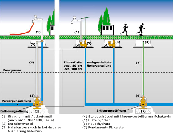
A sampling standpipe (1) with hose connection or with outlet valves can be mounted directly on the bayonet connection. An integrated backflow preventer in the standpipe or outlet valve with pipe aerator and backflow preventer is an advantage.
Thanks to the tapping valves (2) connected in series, the water tapping points are always where they are actually needed. The supply lines to the withdrawal valves do not have to be in the frost-free area, as the entire network is emptied with the closing process over the main hydrant – and then opening all the withdrawal valves. The dispensing valves are mounted in sturdy tap boxes (3), which are also available in a drive-on version.
The ascender wrench (4) – in a length-adjustable, robust protective tube – is used to open and close the single (5) or main hydrant (6).
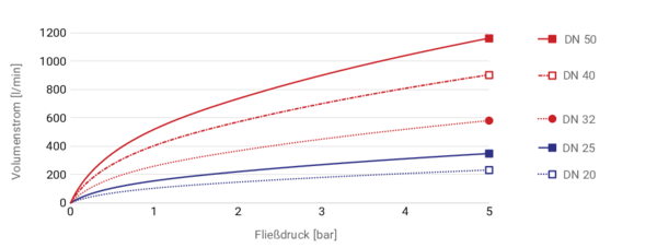
The main hydrant (6) has internal threads on both sides and, like the single hydrant (5), is supplied ready for installation in sizes from DN 20 (3/4") to DN 50 (2").
When the hydrants are closed and the extraction valves (2) or the removal standpipe (1) is dismantled, the entire downstream pipe network runs empty. This guarantees absolute frost resistance even on the outgoing side.
Main and individual hydrants are designed for use in the ground at frost-free depths. When shut off, the hydrant and thus the downstream or ascending pipelines empty automatically. When the hydrant is opened, the discharge opening is closed by the shut-off piston. During installation, care must be taken to ensure that the pipes to be emptied are laid with a sufficient gradient towards the hydrant so that the drained water can drain out completely and seep away (soil). The bottom flange plate of the hydrant must be anchored in the ground (foundation stone) in such a way that the hydrant is secured against twisting and subsidence. The connecting pipeline between the outlet manifold of the single hydrant and the guide disc can be created on site. The guide washer must be screwed to the web of the tap box. Corresponding boreholes are available for this purpose.
It is recommended to secure the riser wrench to the operating square of the hydrant with a stainless steel cotter pin to prevent it from being pulled out unintentionally. The protective pipe must be installed so that the operation of the hydrant is not hindered by the soil, stones or dirt. When closing the hydrant, a torque of 40 Nm must not be exceeded. The hydrants must always be opened fully, they must not be used as a throttle or regulation valve because they are emptied automatically. The upper parts and seals of main or individual hydrants are not interchangeable. The fittings are maintenance-free.
Single Fire Hydrant Sets
like other hydrants, they are designed for use in frost-free areas under the ground. When shut-off, the entire installation on the outlet side empties automatically. All individual parts in the ground are completely pre-assembled ex works, for different installation depths. During installation, it is only necessary to ensure that the emptying water can seep into the ground without any problems (coarse-grained gravel bed).
Extraction valves
are to be screwed to the web of the tap box on site with the fastening flange. The valves can also be attached to the foundation plate of the tap box. The upper parts of the removal valves are replaceable.
Validity Instructions
Illustrations and descriptions correspond to the technical state of the art at the time of publication. A liability cannot be derived from the information. We reserve the right to make product changes.
Deliveries are made exclusively in accordance with our General Terms and Conditions of Sale and Delivery.
